Lotte World Tower Model Development
1. Building Information
• Description:
- 123-floor
- 555-meter skyscraper
- The 6th tallest building in the world
- Opened on April 11, 2017
- Served for hotel, residence, and offices


2. Parametric Mass Design
First, multiple reference planes were created to make a truss parametrically work. Based on the planes, reference lines were created to shape the basic form of the truss body.

Along the reference line, a round shape form was created.
The sizes (width & length) of the top and bottom rectangular were set to be half of the size (width & length) of the middle octagon.

An adaptive family consisted of two adaptive points and one reference line was loaded into the body truss and created the remaining part of the truss.

An angle between two yellow lines was set to be parametrically changed.
The first trial for making the outer walls by picking red parts of the truss was failed due to the reason that the red truss was exposed outside the wall and made the model look ugly. Also, the adaptive family for the red truss was created based on the reference line which doesn't allow creating a form when the model is loaded into a conceptual mass. To solve this problem, an adaptive family having seven adaptive points with curve model lines was created, loaded into the truss family and attached to the outside of each part* of the red truss (*each part = four parts separated by yellow parts).

Multiple trusses with different sizes and parameters were stacked in the vertical direction to form the bottom part of the model.

A form was created based on the adaptive family created in the previous process. Further work was done to make a curtain panel on the outside wall.

For the top part of the model, a simple curve was created and placed on the top to form the remaining part of the model. The curve form was connected to the top edge of the bottom part.
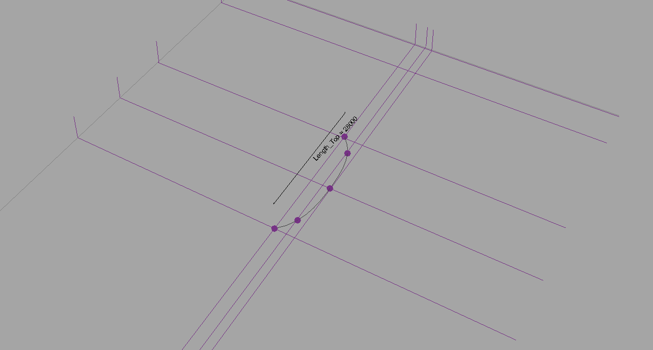
Since the top curve was created based on multiple points, it is not a curve having a smooth line. Due to this reason, the form created based on this curve and the top edge of the bottom part had somewhat irregular shapes and resulted in errors when using default curtain panels. Therefore, in the process of designing the facade for the top part, an adaptive family was used and attached manually instead of using curtain panels.

3. Facade Design
The facade was created based on a rectangular curtain panel. The panel works parametrically with the size of the wall placed on each side. The material for the center part was set to be glass.

The panel was attached to the surface of the bottom part of the model.

For the top part facade, a triangular shape adaptive family was created.

The adaptive family was attached on the surface of the top maually.

4. Final Model


5. Parametric change test
5.1. Mass part
This is the original truss model
It can be parametrically changed with the size of the mass (120m -> 90m)

The angle for the two separate parts of the truss can be changed (30 degree -> 50 degree)

The size of the top part of the blue-colored truss can be changed separately (45m -> 35m)

5.2 Facade part
This is the original facade model

The angle for the facade can be changed (90 degree -> 45 degree)

The thickness of the sidewall of the panel can be changed

6. Project Movie
7. Limitations & Considerations
ChallengesThe most difficult part of the model development was making the complex octagonal truss model work well with parametric change. The more the model is getting complex, the more constraint errors I encountered. Lines, edges, etc. are all in the same position, so it was too difficult to keep paying attention to click the right one. I developed the model without any sketch or CAD model, so it was too tough to make it right away.
Limitations
The truss model that I developed has some invisible constraints for sizes. Due to some inflexible lines and angles, the size of the truss can't be smaller than 63 meters.
Compared with Rhino model
Compared to the Rhino model that I developed in ARCH 655 course, the Revit model is much more complex to build and need time due to trial and error processes for the line selection since the Revit has too many geometry details. On the other hand, the Revit model has more capability for future usage because of the details.
Comments
Post a Comment